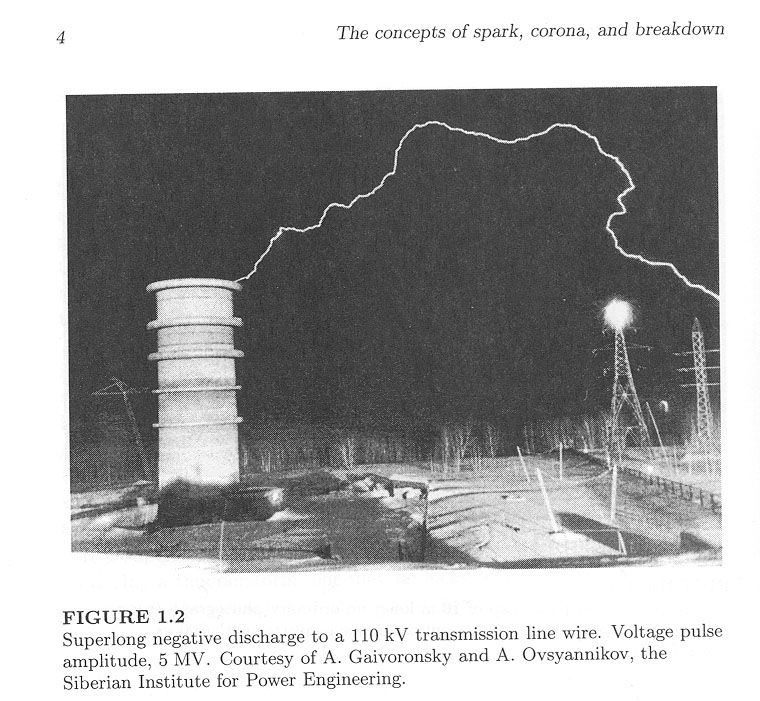
- World's longest (150 meter) man-made spark from the SIBNIIE High Voltage test facility in Siberia (RIP)
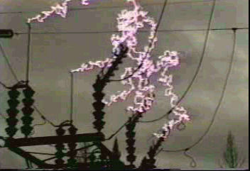
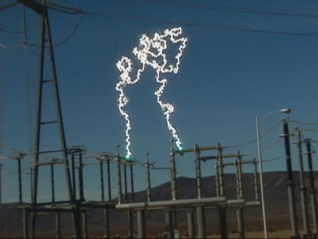
- 230 kV MPEG and 115 kV image of three-phase air break switches opening "hot"
- Video of a 500 kV switch creating a 100+ foot arc when one phase accidentally opens "hot"
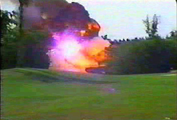
- Video of an an arcing fault that causes a 138 kV substation power transformer to explode
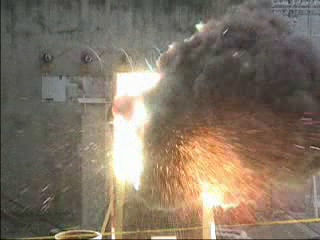
- Video of a high energy 480 volt 3-phase arc flash initiated in a testing laboratory
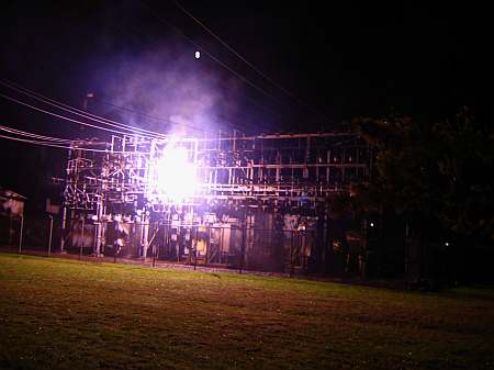
- Video of an arcing fault in a substation when a high voltage fuse fails to open cleanly
- Link Belt crane tangles with a 46 kV feeder, explodes concrete (from Federal OSHA Site)
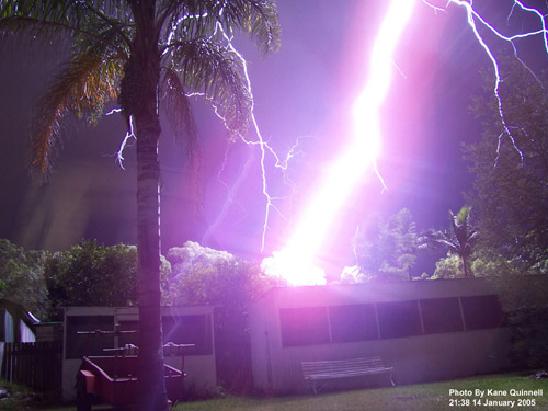
- IA huge positive lightning bolt almost strikes an Australian lightning photographer
- Video of Dueling "Mario Bros." Tesla Coils zap a daring Tesla Coiler with 12 foot sparks
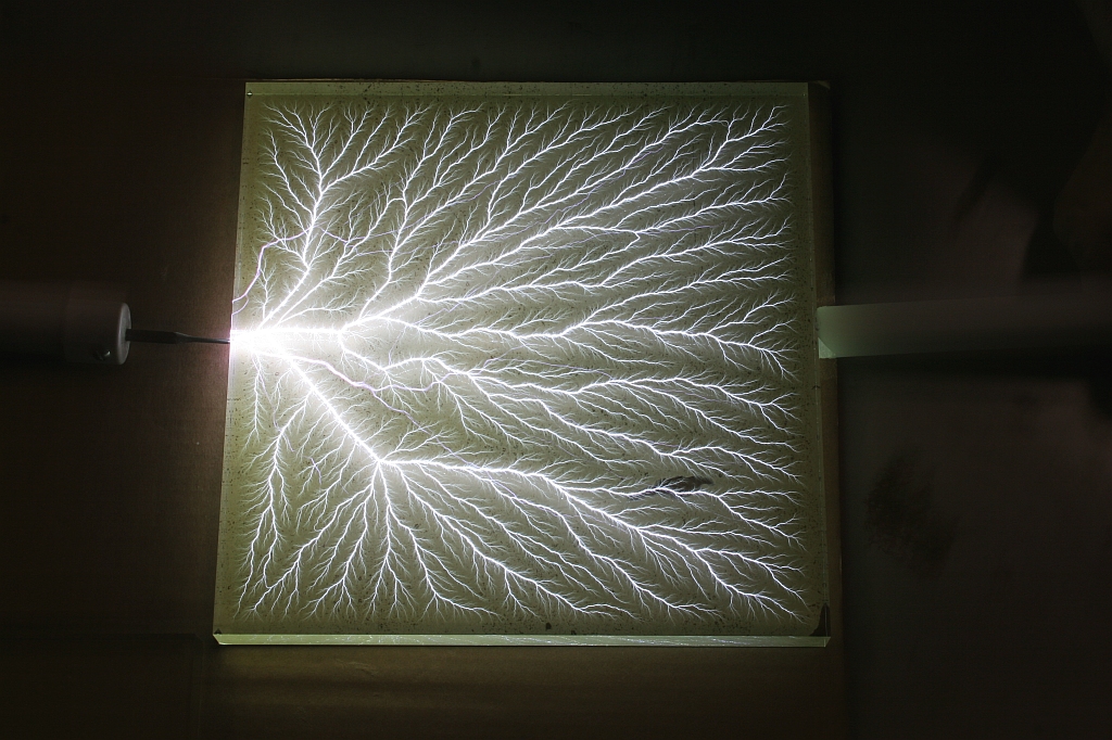
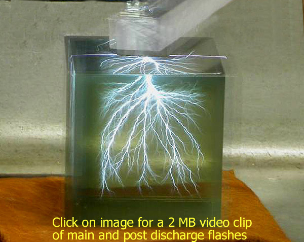
- A 2.2 million volt "lightning bolt" is captured within a 12 x 12 inch slab of clear Plexiglas
- Video of a huge 15" x 20" x 2" Lichtenberg figure being created by a 2.5 million volt discharge
- What happens when a live HV power line falls to the ground?
The cylindrical object on the left houses a multi-million volt (MV) high voltage impulse generator, called a Marx Generator, at the Siberian Power Research Institute high voltage testing facility in Novosibirsk, Siberia. The positive polarity and rate of rise of the voltage pulse from the Marx Generator maximized the "efficiency" of creating long sparks. Although first reports of huge 100+ meter sparks were initially met with skepticism by scientists and high voltage engineers, a number of power engineers and scientists have subsequently witnessed similar events at this facility. Sometimes these errant bolts hit the top of street lamps in the adjacent parking lot! At this facility, sparks up to 200 meters long have been created using a comparatively low potential of 5.2 MV. In order to gain a feel for scale in the above photo, the cylindrical building is 28 meters (~92 feet) high, and it houses a 28-stage Marx generator that's capable of generating positive or negative output pulses of up to 7 million volts. The building is constructed of closed-cell polyurethane foam, about 1 meter thick to withstand the high voltage stress. In late 2005, a member of the Tesla Coil Mailing List (Dmitry, a Tesla Coiling enthusiast who lives near
the facility) was able to schedule a visit with members of their staff.
Dmitry subsequently shared details about this facility in a series of
email messages to the other members on the list, and the excellent pictures he took can be
seen on our mirror of Terry Fritz's old Hot-Streamer web site.
A video slide show of this facility can be also be seen on YouTube.
Through his efforts, we now know that the SIBNIIE generator uses 896
energy storage capacitors, each rated at 175
nF @ 125 kV. Each stage of the Marx uses thirty two capacitors to create
an equivalent stage capacitance of 1400 nF at 500 kVDC. However, in
order to prolong capacitor life, each stage is limited to 50% of this, or a
maximum of 250 kV. The fully charged "erected capacitance" is ~50 nF and, at maximum
output, the generator develops 1.225 million Joules (MJ) per shot. In the above discharge, the
maximum voltage was approximately five million volts, resulting in a point to point
discharge of ~70 meters (230 feet). The estimated actual spark channel
distance was ~150 meters (~492 feet). The pulse rise time was ~150 usec, duration was ~10
milliseconds, and the overall Marx bank energy was ~678 kilojoules. An even larger Marx generator resides at the High Voltage Research Center (HVRC) in Istra, Russia. The facility was designed and built by the former German firm TuR, and was commissioned by Siemens. The facility is also the home of the world's largest AC Test Facility, with cascaded transformers capable of delivering 3 million volts AC at 12 million volt-amperes (MVA). The huge Istra Marx generator towers 43 meters (141 feet) high, and consists of fifteen stages. Each stage is capable of operating at a maximum of 600 kV. Each stage has a huge external voltage-grading ring to help equalize the voltage stress across the tower and to prevent unwanted corona or flashovers. The Istra facility is designed to generate a maximum of 9 million volts at an erect capacitance of 150 nF. It is normally operated at a maximum of 6 million volts (~1.3 megajoules per shot) in order to prolong capacitor life. The following images show a daytime view of the Istra generator, and a man-made lightning bolt at night. Two incomplete leaders can also be seen issuing from the top toroid. Another unexpected branched leader can also be seen coming from the lower 12th stage grading ring. This generator has produced open air sparks as long as 150 meters (492 feet)! July 2025 update: and Vladimir S. Syssoev and Yuri V. Shcherbakov. ![]() ![]() Through high-voltage research at facilities such as these, it has been determined that switching surges on Extra High Voltage (EHV) electrical power transmission systems can initiate conductive plasma channels, called streamers, which can quickly lead to flashovers to other phases or ground, causing disruptive circuit breaker trips and unplanned service outages. The formation and growth of positive streamers may be a limiting factor for practical EHV power transmission system design. This phenomenon may place an upper voltage limit for AC transmission of about 1.2 million volts. As of 2025. the highest operating AC transmission voltage was 1.15 million volts, used in the Powerline Ekibastuz Kokshetau, a 696 kilometer, three-phase transmission line that connects hydro power generating plants in Western Siberia, through Kazakhstan, to Russia. A 1.1 MV transmission system is also operational in China. However, India plans to implement an experimental 1.2 MVAC transmission system at their UHVAC testing facility at Bina in Madhya Pradesh. The Power Grid Corporation of India (PGCIL) plans to apply experience gained from this test facility to convert a 400 km transmission line (connecting Wardha and Aurangabad) from 400 kV to 1.2 MV, increasing the capacity of these transmission lines from 400 MW to over 6,000 MW.
"Electrical Strength of Ultra-Long Air Gaps", International Conference
on Lightning and Static Electricity, September 2001, Seattle, WA)
|
I recently received new information regarding this video from Wally Groff, a Journeyman Operator at Bonneville Power Administration (BPA). This video was captured in 2002 at a BPA substation located at the Haskill tap of the Libby-Conkelley No.1 230 kV transmission line near Kalispell Montana by Wally's supervisor. It shows a three phase vertical break disconnect switch attempting to de-energize an unloaded 34 mile long section of transmission line. This switch was part of an experimental design and is no longer in service. Air break disconnect switches are not intended to actively switch load current. In the above clip, the arcing is due to the attempted interruption of comparatively low reactive (capacitive or "charging") currents drawn by the open transmission line. Even with reduced current, the disconnect switch was not always capable of opening the circuit. At the very end of the clip, a brief phase-to-phase power arc causes a short circuit, tripping upstream interrupters and finally extinguishing the arcs.
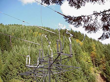
Wally was also kind enough to provide the following image of another disconnect switch that failed to open properly. This was a 115 kV quick break disconnect that had exceeded it's switching capability while attempting to de-energize a 24 mile section of transmission line at a BPA facility near Tillamook, Oregon. At times the disconnect switch operated properly, but not this day. As can be seen, one phase successfully disconnected, but the other two phases did not. Luckily the operator was able to re-close the disconnect before it relayed out.
Click for larger image
|